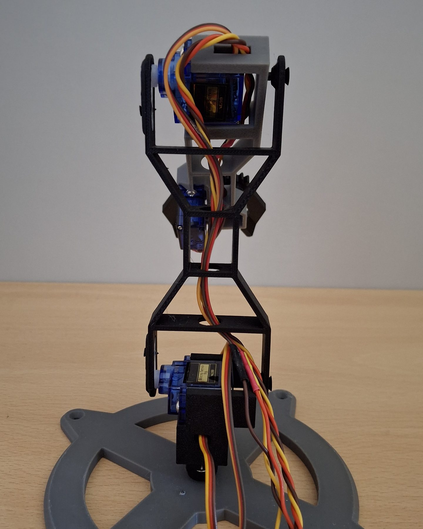
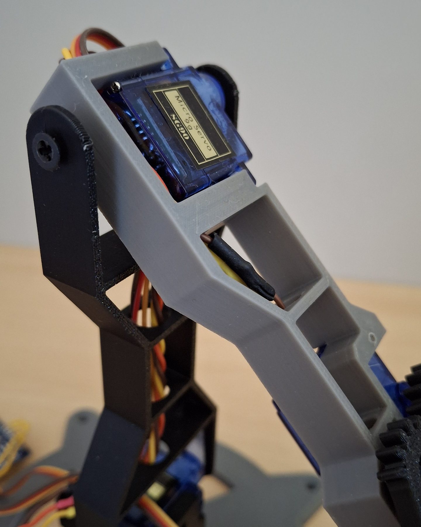
Gripper, left jaw
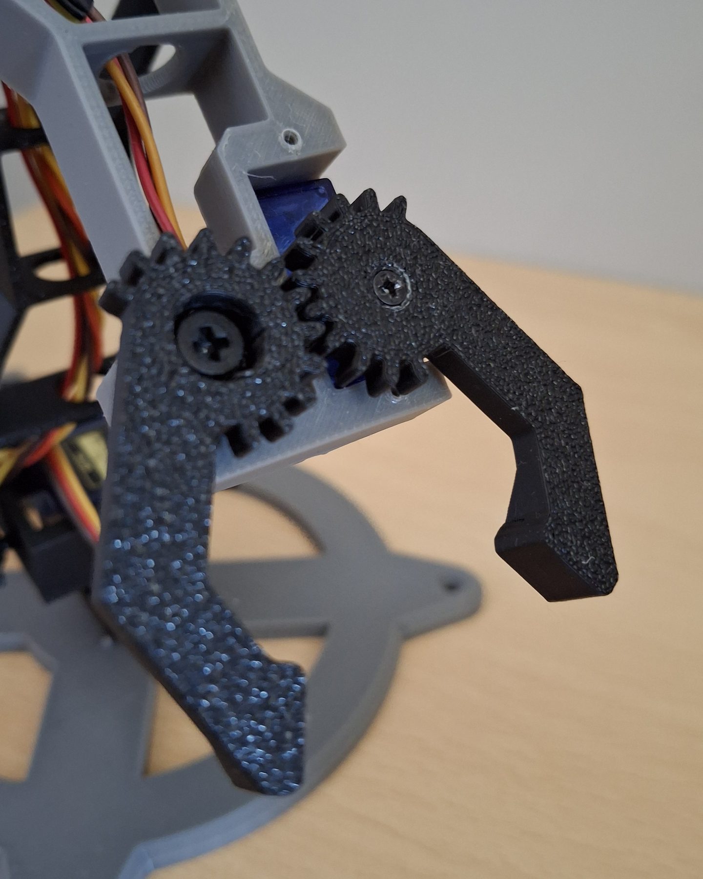
arm_gearThe left jaw of the gripper, with the gear that makes it close against the other.
MaterialPLA
2025
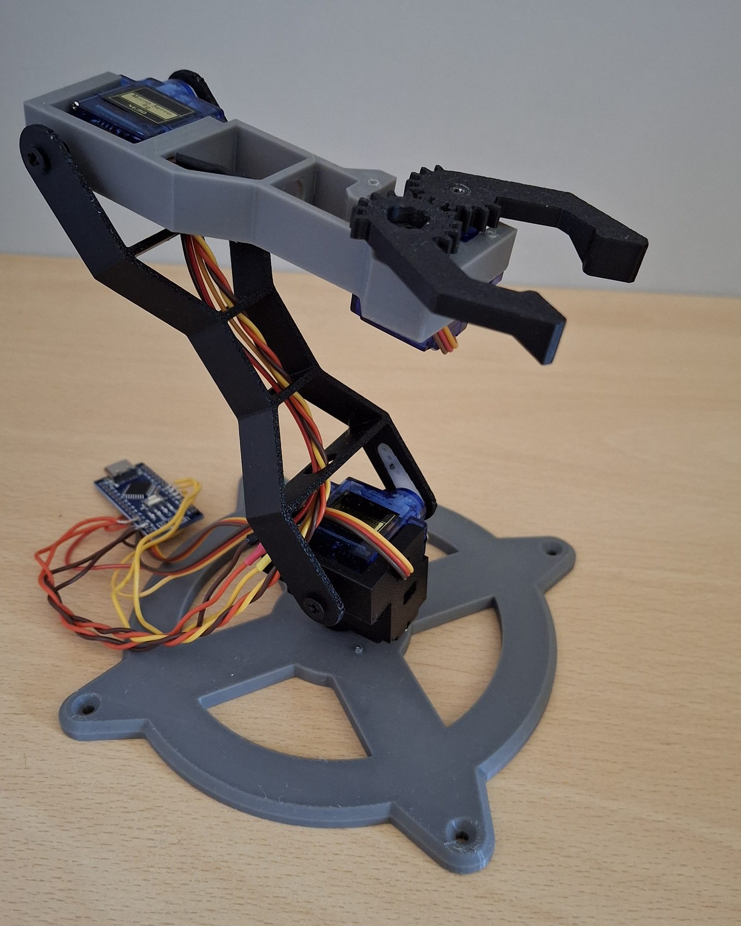
Every part below is clickable. Open one to see what it is and where it sits. The Servo Mini Arm is the simplest robot arm I could design that still does something useful: six printed parts, four 9 g servos, two servo extension cables, a few M3 and M2 screws and an Arduino. It was published on MakerWorld in April 2025 with a four-page assembly sheet, and updated twice after the comments of the people who built it: a mod that avoids cutting and soldering the servo cables, and a new base with a cover for the Arduino.
FilesFree on MakerWorld: the 3D files, a print profile and the assembly guide in PDF. The code is on GitHub.
Files and guide on MakerWorldmakerworld.com ↗Source code on GitHubgithub.com ↗Every printed part, with its function and print settings.
The left jaw of the gripper, with the gear that makes it close against the other.
The right jaw, mounted on the gripper servo: turning, it moves the left one through the gears.
The ring-shaped foot, with four holes to fix it to the desk. The cross horn of the base servo is screwed into its centre.
The block on the base that holds two servos back to back: the one below turns the arm, the one above lifts the first arm.
The lower segment, an open frame with a servo horn screwed into each end: the shoulder servo below, the elbow servo above.
9 g digital servos with clutch protection: a continuous-rotation one in the base, three 180° positional ones at shoulder, elbow and gripper. The servo arms connect through two 200 mm extension cables.
The upper segment: it holds the elbow servo at one end and the gripper servo at the other.
The bracket that holds the gripper servo on the second arm.
The single-arm horns that come with the servos, screwed into both ends of the first arm.
The cross horn that comes with the servo, screwed into the centre of the base: the base servo turns against it.
Electronics
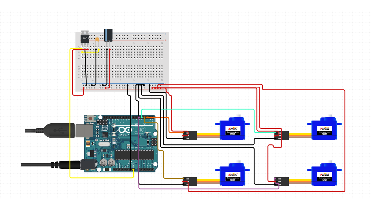
Two servos sit back to back in the block on the base: the lower one, continuous-rotation, turns the whole arm against a cross horn screwed into the base; the upper one lifts the first arm. A third servo at the elbow moves the second arm, and a fourth closes the gripper through a pair of gears. For a first test every servo goes straight to the board: positives to Vin, negatives to GND, each signal to its own digital pin (3, 2, 4 and 5 in the example code). The full diagram powers the servos from an external supply through a 7805 regulator, with a capacitor that keeps the arm steady when several servos move at once. The diagram uses an Arduino Uno, the photos a Nano: any board with four free pins will do.
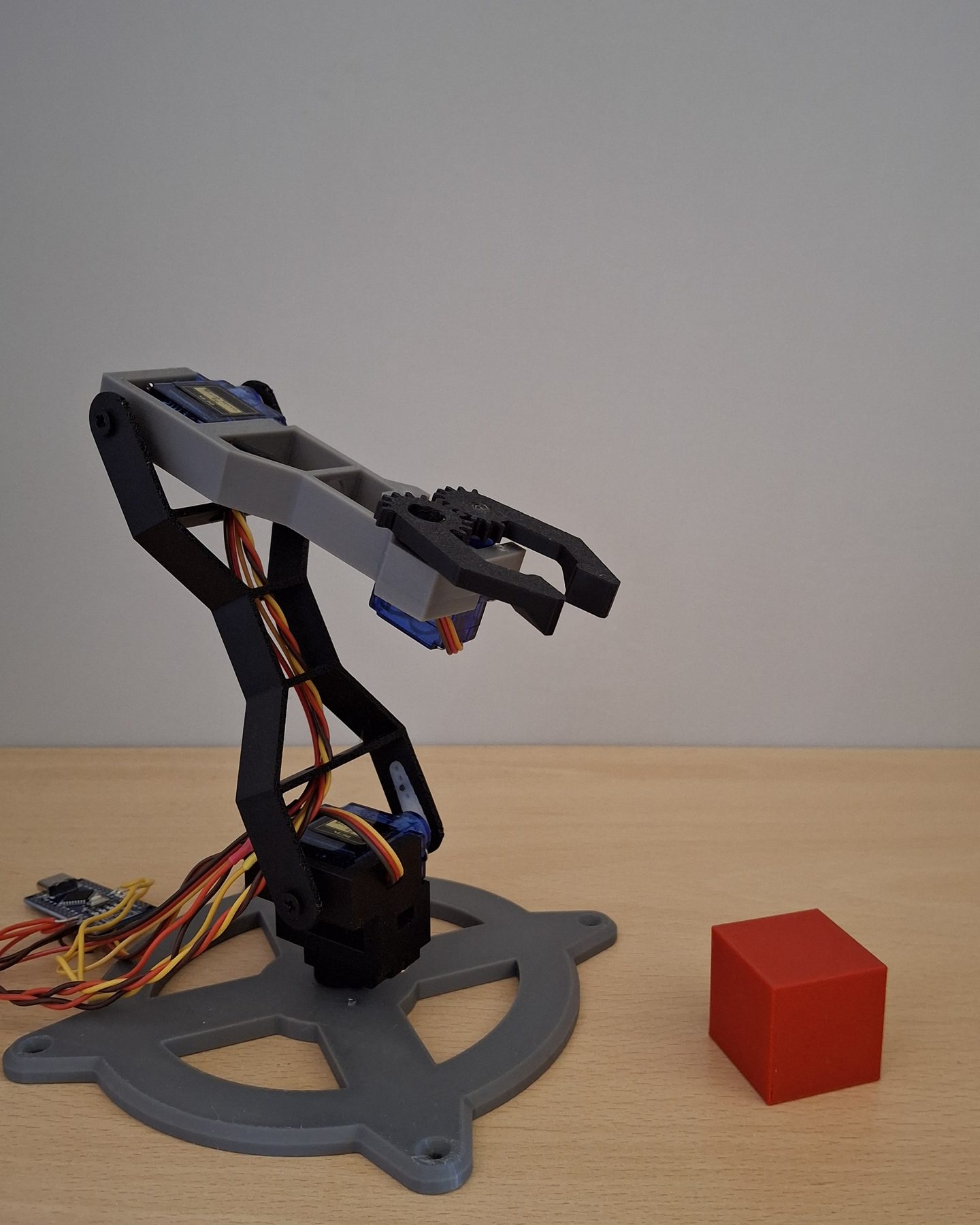
Software
The example sketch on GitHub runs one sequence at power-on: it opens the gripper, lowers the first arm onto a cube, closes, lifts, turns the base, reaches out with the second arm and lets the cube go, then goes back to rest. It is a few dozen lines with the standard Servo library, written to be changed. People who built it have driven it from a phone app over Bluetooth and from a web page served by an ESP32.